Beginning Work
HiWIRE® strives toward a minimal set of carefully chosen features. However, these few features can be combined in quite simple ways to multiply their effect and achieve a much more powerful result. There are only a handful of concepts to grasp before you're productive. You'll find the frustration level is substantially lower than with some other approaches.
HiWIRE® uses Python® for scripting and aspires to its ideal of One Obvious Way. If you prefer to have Many Ways To Do It, play along for a while. You may find you like it.
You should certainly try out things you see on this and subsequent pages.
Start with an empty drawing and don't worry about it if you accidentally wander astray. Although HiWIRE® allows up to 256 layers, the early examples use only one. The illustrations make a few adjustments so things are easier to see, but you should be able to follow along anyway.
Creating Things
HiWIRE uses only five primitive object types:
Lines – a set of two or more vertices connected by a sequence of one or more straight segments. Conceptually, the segments are rendered by a fixed-width, round stylus. Under sufficient magnification, you can see a line has rounded ends and joins at each vertex. Lines are used to connect components in a schematic drawing or board layout.
Pads – A special-purpose, filled convex figure. The name comes from the days when circuit boards were designed using rolls of narrow tape to form connections between adhesive-backed donut pads. These pads described where component pins would be soldered. HiWIRE pads can be ellipses or rectangles. Conceptually, rectangles are rendered by a smaller circular stylus which rounds their corners. Rectangles can collapse into ovals or circles when your design requires it. HiWIRE uses circular pads as schematic connection dots and to specify where holes should be drilled in your circuit board.
Labels – Annotating text you specify by typing at the keyboard. Conceptually, labels are rendered as a set of lines as described by a font. A single font may use multiple linewidths; the built-in font does not.
Arcs – A curved (circular) line defined by its center, radius and included angle. Conceptually, arcs are rendered by a fixed-width round stylus, just like lines. Circles are simply 360-degree arcs. Arcs are rare in circuit board layouts, but appear more often in schematics and assembly drawings.
Polygons – a set of three or more vertices defining a convex region with a filled interior. Polygons are sometimes used in circuit boards to represent areas of copper ground plane.
Inserting a primitive into your drawing is as easy as 1, 2, 3:
 |
Figure 3A |
Move the cursor into the parts bin containing the item you want to insert. Press and hold the left mouse button.
Holding the button pressed, drag the object into position. As you move the cursor, the object will snap to grid. If you want to shift the item off grid, press and hold the Shift key on your keyboard.
When the item is positioned where you want it, release the mouse button to leave it at its final position.
The items you insert this way are in embryonic form, and will you'll almost always morph them into something more useful. But, we'll return to that later on.
Some characteristics are controlled by the Preferences dialog, displayed by Edit->Preferences… and can't be interactively changed: line width, arc width and text size. Although pad dimensions can be changed manually, it becomes a tedious process when many pads are involved. You're better off deciding a pad's geometry in advance and setting Preferences so you don't have to change your pad later.
Moving Things
If you're dissatisfied with how you positioned an item, don't despair. You can quickly move it.
Pick the item. That is, move the cursor to point at the item. Unless you made an unfortunate color choice in your Preferences, the item's appearance will change. Also, the status line will flash up some information about the picked item.
Press and hold the left mouse button and drag the item to its new position. As with inserting a new primitive, Shift disables snap-to-grid.
Release the button when you're satisfied with the item's new position.
During a long-distance move or a fine, off-grid positioning, holding the left mouse button down can become quite tedious. You can use the right button to press-lock the left. To end the locked drag, click the left button.
Duplicating
Sometimes you find HiWIRE's parts bins are loaded with the wrong size pad or a too-thin line. Although it's fairly easy to change the Preferences, it's even easier if the perfect object already exists elsewhere in your drawing. Just make a twin!
Pick the item as if you were going to move it.
Before you press the mouse button, press and hold the Alt key to move an alternate item instead of the original.
Complete the operation as if it were a move. The original will remain it its old location.
Figure 3B, below, shows the result of applying this operation six times to the pad placed earlier. The operator is positioning the last duplicate into what appears to be a SIP footprint.
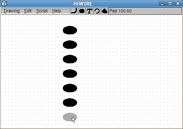 |
Figure 3B |
Although Shift and Alt were mentioned in conjunction with Moving and Copying respectively, the two keys are interchangable. You can use Alt to disable snap-to-grid or Shift to duplicate an object. HiWIRE even allows a third equivalent, the Ctrl key. This comes in quite handy if, for example, your system switches desktops by clicking the mouse with the Alt key pressed.