Making Changes
With HiWIRE®, expect to spend most of your time loading parts from a library and interconnecting them with lines. These parts, usually schematic symbols or PCB footprints are nothing more than simple groups; and most were created for you using the select-and-bind technique you saw earlier.
Of course, there are special rules for defining parts, naming signals, creating libraries, etc. You may catch a glimpse of these rules in the discussion that follows, but the rules aren't important yet. We'll revisit them in much more detail later.
Primitives from the parts bins are in embryonic form, and you must change them to fit your design. Parts from a library can have placeholder labels you'll need to modify. E.g., a capacitor's placeholder value may need to be changed from its initial nn pF to your intended 470 pF.
In either case you're altering a HiWIRE® primitive. For each of the five primitives, a different technique is used. However, the same technique can be applied whether or not the primitive is part of a group.
Preparing for Change
Before changing a primitive, you must select it. To select a primitive that belongs to a group, select the group. You can tell a primitive is selected if it is adorned with knobs.
When assembling and dismantling groups, knobs are little more than decoration, When changing primitives, knobs play a vital role as the change progresses.
Changing a Line
A selected line displays knobs:
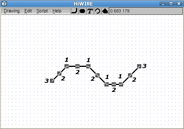 |
Figure 5A |
At each interior vertex,
At the midpoint of each segment, and
At each end,
Although it will become quite natural, the technique you use depends subtly on which of the the knobs you're manipulating.
Bending a Line
To move a vertex, point the cursor at its knob, press the left mouse button, drag it where you want it, and release the button. (Don't forget, you can use the right mouse button to press lock the left button and the Shift key to move off-grid.) The changed line has the same number of segments as the original:
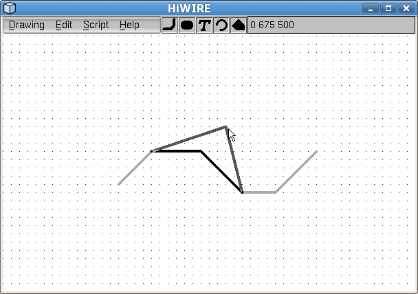 |
Figure 5B |
An interior vertex being moved. The original line is shown for reference purposes only.
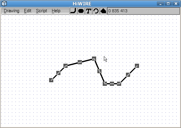 |
Figure 5C |
The move is complete. The line remains selected in anticipation of further changes.
Use the same technique to bend a line at a segment midpoint. The changed line has one more segment than the original.
Extending a Line
The operation is much easer in the doing than the telling:
Click on the endpoint knob to extend the adjacent segment.
Move the mouse (with no button depressed) to alter that segment.
Click the mouse to end one segment and begin another; repeat as required.
Use the Backspace key if you misplace a vertex!
Use the Esc key to trim the last segment and leave the rest.
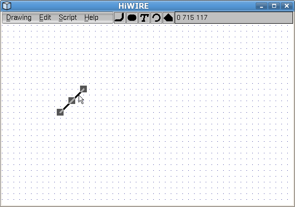 |
Figure 5D |
A brand new line, just after dragging it in from the parts bin and clicking it to expose its knobs.
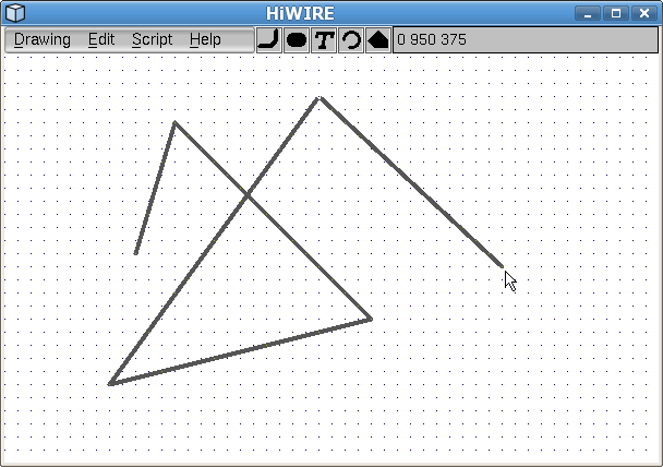 |
Figure 5E |
The changing version after extending its topmost endpoint with four clicks. The final endpoint tracks the cursor, but the adjacent segment is not yet part of the line.
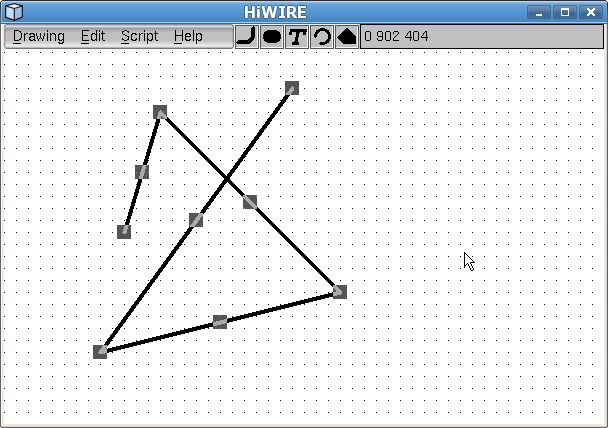 |
Figure 5F |
After pressing and releasing the Esc key on the keyboard, the final segment is discarded. The 4-segment changed version is selected in anticipation of further changes.
You can constrain lines in your schematic diagram to run only horizontally or vertically, or you can force traces in your circuit board to run at multiples of 45 degrees.
If in Edit->Preferences…, lock is set to 45 or 90, the segment being extended will be displayed as two segments, constrained to run in only the (inter)cardinal directions. The segment further from the cursor is the one you'll add when you click. The nearer segment is only there to aid in alignment.
Bending the End
You can also drag the knob attached to an endpoint in exactly the same way you drag an interior vertex. The difference is that you'll need to use the Esc key to keep from extending the line.
The lock setting in Edit->Preferences… has no effect when you're dragging a vertex.
In digital designs, arrays of parts are often interconnected in a very repetitive fashion. The PCB trace connecting address pins of two ROMs in an eight-ROM array can usually be rubber stamped to connect the other six.
Copying is almost always easier than creating.
Changing a Label
Click the label to expose an ornate knob.
Click the knob to display the label-change dialog.
Change the label text (the portion you see in your drawing) and attribute (a addtitional, invisible portion you don't).
Click the OK button or press Enter to confirm the change, or click Cancel if you change your mind.
Attributes are used to to add semantics to the label. If you don't know what this means, don't worry; we'll revisit this idea later. For now, just understand the attribute allows you hide some extra information inside a label. This hidden information is duplicated if you copy the label and follows the label when you move it.
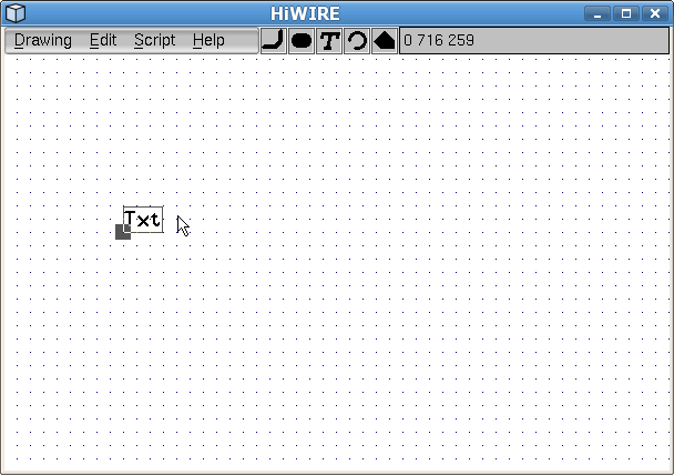 |
Figure 5G |
Figure 5G shows a size-30 label fresh from the parts bin. The embryonic “Txt” is almost certainly not what you want. After selecting the label, it displays the usual square knob below and left of the label, but the knob features an attached bail that encloses the entire visible text.
The knob at the lower-left of the selected label above is centered on the label's hotspot. The hotspot is the “business end” of the label. As you move the label around your drawing, it is the hotspot that snaps to to the dot grid and aids you in aligning the hotspot with conductors.
As you rotate or flip the label, its hotspot stays in the same relative location. If you're unsure where the hotspot is, select the label to find out.
Because labels are so frequently changed, HiWIRE makes them much easier to pick. When selecting a label, you need not point precisely at one of its characters; pointing anywhere within the area enclosed by the bail is close enough. When changing a label, you need not click inside the square knob; click anywhere inside the enclosing bail.
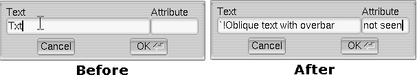 |
Figure 5H |
On the left, observe the original label has three characters and no attribute. As you move the cursor into the Text or Attribute entry area, the cursor changes to an I beam to invite you to use your the bag of text wrangling tricks: click-to-insert, drag-to-select, double-click-to-select-word, triple-click-to-select all, etc.
In digital design, a text overbar is sometimes used to distinguish an inverted or active-low signal. If you want your label text to be rendered with an overbar, prefix an exclamation point ( ! ).
For oblique text, prefix an accent grave ( ` ).
If you want an overbar above oblique text, use the prefix `!; the reversed order won't work.
On the right, the label text has been revised to `!Oblique text with overbar, and a nonsense eight-character attribute has been added: not seen.
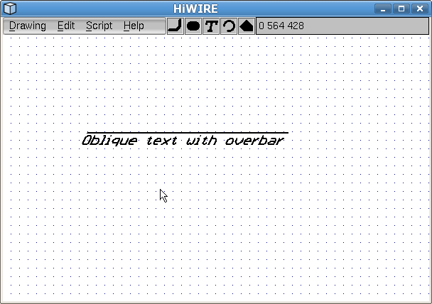 |
Figure 5I |
After approving the change, the changed label remains selected for consistency. Figure 5I shows the label after deselecting it. The invisible attribute has no effect on how it looks in your drawing.
Changing a Pad
It's better to specify the size and shape of the pad you want to use in the Edit->Preferences… dialog before creating the pad, but as a last resort, you can change the size and shape of an existing pad.
Click the pad to expose a knob at its center.
Click the knob to change the pad to the size and shape specified in the Edit->Preferences… dialog.
Changing an Arc
Fresh from the parts bin, an arc has a 90-degree included angle. Unless disabled by the Shift key, the arc center snaps to grid as you jockey it into position.
A selected arc displays a knob at each end. You can drag either one to change the included angle or radius. The arc center doesn't move.
To change an arc to a circle, drag one end all the way around to meet the other. Once the ends touch, they are welded together. You can change only the radius of a circle by dragging the single handle at the point of the weld.
Changing a Polygon
HiWIRE polygons are convex. That is, if any two points inside a HiWIRE are connected by a straight line segment, the segment falls inside the polygon.
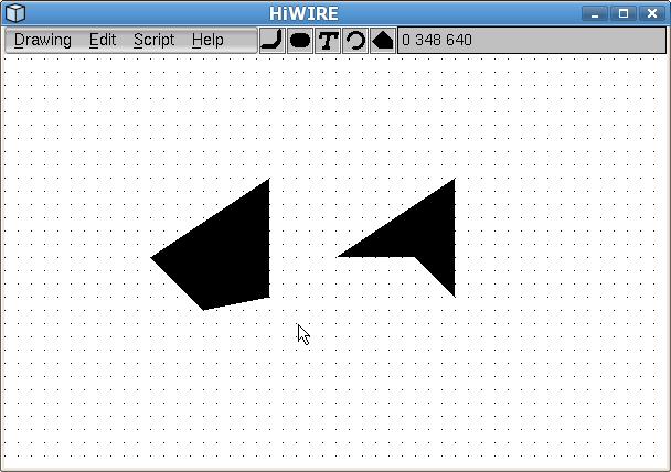 |
Figure 5J |
Figure 5J shows two quadrilateral polygons. The one on the left is convex; the one on the right is not.
When changing HiWIRE polygons, it may be helpful to contemplate an elastic band stretched around pegs inserted into a board. The pegs are the vertices of the polygon; the polygon is the interior of the band.
An extra peg interior to the stretched band doesn't affect its shape until it is moved outward and begins to engage the band. Conversely, if a peg is dislodged and moved inward, it eventually enters the interior and ceases controlling the band's shape.
 |
Figure 5K |
Selecting the left quadrilateral exposes five knobs. You can drag any knob to change the polygon's shape.
Dragging an exterior knob into the interior reduces the number of sides.
Dragging the interior knob to the exterior increases the number of sides.
But take care! If, while moving a knob, the figure swallows one of the other external vertices, it also reduces the number of sides.
Going concave
The quadrilateral on the right in Figures 5J and 5K is not an illusion. It was drawn in HiWIRE. If HiWIRE polygons can only be convex, how is this possible? Picking the figure reveals how it was done:
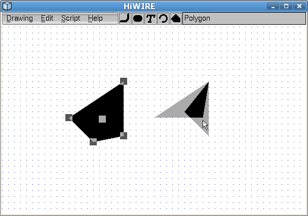 |
Figure 5L |
Observe the four-sided figure is just two overlapping triangles. Awash in the highlight color, the region of overlap appears darker.
Why are both triangles highlighted when only one is picked?
Hover here for the answer.