Setting Preferences
You can control HiWIRE® behavior in various ways: display of physical units; the dimensions of pads, lines arcs and labels in the parts bins; the angle lines are allowed to run, etc. This all happens on the Preferences dialog, displayed by Edit->Preferences… on the menu.
You can change the settings and then click Close to hide the dialog, or leave it displayed while you work in the main window. This facilitates quick changes (e.g., to a wider line for a power-distribution trace on your circuit board).
Choosing Units
Place your cursor atop the Units: widget and press the left mouse button to pop up a menu of choices. By default, HiWIRE allows you to use inches, mils (1 mil = 0.001 inches), or mm (1 mm = 0.001 meters) displayed to a precision of 3, 0 and 1 digits (right of the decimal point), respectively.
Although HiWIRE rounds dimensions for display, rest assured any actual values you enter are preserved to the full accuracy supported by your computer's hardware.
For example, if your preferred units are mils, and you enter a grid spacing of 12.2 or 11.8, both may be displayed as 12, but at high magnification, the latter will be a bit more finely spaced.
HiWIRE's default units are consistent. You can change your preferred units between any of the three settings, and, although the displayed numbers change, the sizes remains the same.
You can change HiWIRE's default mil, mm and inch units to ones more suitable for your application domain, but we won't address that now.
Defining Pad Shape
To set the size of pads in the parts bin, enter the desired Pad Width:, Height: and corner Diameter: into the provided text boxes. HiWIRE displays a sample of your revised pad in the Preview area and round your dimension for display (but see Note, above).
The corner diameter affects the shape of the pad:
 |
Figure 9A |
Figure 9A shows a pad whose perimeter is defined by the sweep of a round aperture moving along a rectangular path.
To make a true rectangle, set the corner diameter to 0.
To make an oval pad, set the corner diameter to the smaller of the width or height.
To make a round pad, set the width, height and diameter equal.
Elliptical Pads
Some fabricators claim that using elliptical pads for through-hole components will reduce board manufacturing defects and increase long-term reliability. HiWIRE supports elliptical pads as well as the more conventional shapes.
To specify an elliptical pad outline, enter the height and width as normal, but enter two dashes (--) for the width.
The size and shape you specify in the Preferences dialog also dictates the result of changing a pad.
Setting Line Width
Enter the required width in your prefered units into Line Width:.
For a dotted line, enter two periods (..). For a dashed line, enter two dashes (--).
Controlling Text Size
To set the text size of new labels, enter an integer between 1 and 65535 into the Text Size: field. At the default scale, 1 results in letters about 30 microns high, far too small to read without a microscope. At 65535, each character is nearly two meters high, too big to fit on the largest commonly available sheets of paper, ISO A0 or ANSI E.
Give careful thought to the size of text in your drawing. HiWIRE uses the Text Size: setting as a lower bound on the size of labels that will be shown when your drawing is printed or plotted. Make sure the labels you want to see can be comfortably read and are in proportion to the rest of your drawing.
You'll also use labels to name component pins (e.g., of a component footprint in a circuit-board design). Making these labels substantially smaller assures they won't appear in your production artwork and also minimizes clutter as you proceed with your design. If you need to see these tiny labels, you can quickly zoom in and take a look.
Controlling Change
Beneath the fields that control the sizes and shapes of items in the parts bins are fields that affect properties of objects as you change them.
Specifying Rotation
The Spin Angle: field controls the degree of rotation for Edit->Spin. Enter a counter-clockwise, degree-valued argument to specify the rotation you want. The rotation you specify is rounded to the nearest 1/64th degree.
The default value of -90.00 specifies a quarter turn clockwise.
Setting Line Lock Mode
As lines are changed, the Lock: setting can constrain segments to lie at multiples of 45 or 90 degrees. To select one of these values, click the adjoining check box. To free lines to run at any angle, click the checked box again to uncheck it.
Setting Pick Tolerence
The Hotsmudge: slider controls how accurately you must point at an item to pick it. The tolerence may be changed from about 1 to 4 screen pixels. A larger value may be more appropriate for a higher-resolution screen:
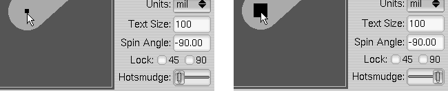 |
Figure 9B |
To change the slider, point at the knob and drag it left or right. The previewed knob gives you a feel for the invisible hotsmudge attached to the business end of your cursor as shown in Figure 9B, above.