Using Libraries
HiWIRE® libraries contain predefined groups you can retrieve and insert into your drawing. Libraries contain, among other things, schematic symbols and circuit board footprints.
HiWIRE® libraries are simple drawing files. Earlier, you saw all the operations required to construct your own library. You must save the drawing in a special place, and there is one special rule you must follow so HiWIRE® can reach inside your drawing and extract a specific group. Here, we'll only discuss using libraries; we'll defer creating them until later.
Browsing the Catalog
To incorporate a library item into your drawing, begin by selecting Drawing->Insert… or use the keyboard shortcut, Ctrl-I. The Chooser dialog appears:
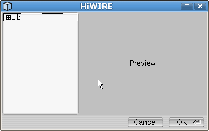 |
Figure 8A |
The left pane displays your available choices in a tree. Initially the tree is collapsed and shows only the root directory. To the left of the directory name is a small box with a + inside. Clicking the name or the box expands the directory:
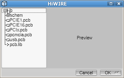 |
Figure 8B |
After clicking Lib, its + becomes a –. Clicking it again would collapse the directory. Here, the root directory, Lib, contains seven things:
A collapsed subdirectory, schem.
Five regular HiWIRE drawings distinguished on their left by tiny drawing icons replete with title blocks in their lower right corner. These drawings are in the special place, but they do not conform to the special rule.
An actual library, pcb.lib, distinguished on its left by an arrow (>), and presumably it holds circuit board footprints.
In some contexts, directories are called folders. HiWIRE's special place is nothing more than a directory/folder. Here, its name is Lib. Later, you'll discover how you can relocate your libraries anywhere you want.
Clicking the collapsed schem reveals it holds six additional libraries:
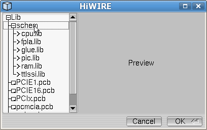 |
Figure 8C |
If you click on a drawing, HiWIRE copies its contents and displays them in the Preview pane. If you approve, the copied data are bundled into a group and inserted into your drawing as if they were loaded from a library.
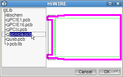 |
Figure 8D |
Observe, schem was clicked to close it, and pcmcia.pcb was clicked to preview its contents. (Perhaps you recognize it as a template for a laptop expansion module.) You can continue to browse by clicking different items in the tree of choices
In HiWIRE, library items and whole drawings are somewhat interchangable.
The former is commonly used for schematic symbols and simple components like those sold by electronics distributors in quantities of 1, 100, 500 and 1000+. A library holds many items in a single file to avoid cluttering your computer with hundreds of tiny files.
The latter is often used to hold templates, common design elements that may include several components along with features that don't belong to any component. Of course, multiple templates could be incorporated into a single library, but there are normally so rare it isn't really necessary.
Here for example, pcmcia.pcb features a footprint for a surface-mounted, 68-pin connector (green) whose ground pins are connected by a perimeter trace (also green) enclosing the space where components will be placed. A 2.5 mm line (magenta) defines the path followed by a 2.5mm CNC tool as it cuts the board outline.
Making a Choice
To accept the previewed object into your drawing, click OK (or press Enter). Or, you can abandon the process by clicking Cancel.
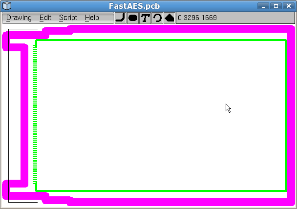 |
Figure 8E |
As you return to your drawing, the item will track the cursor. Position it in your drawing and click the left mouse button to fix it at the desired location.
When loading a large item into an empty drawing, you may only see a tiny portion of the object, or it may be jammed into the corner of the workspace.
Don't forget, you can always zoom in or out as you position the item.
To browse for an item in a library, click its name or the arrow beside it. The arrow will rotate downward, and the contents of the library will be revealed. You may have to scroll down to find the item you're looking for. You can click the library again to collapse its contents and unclutter the display.
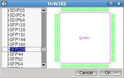 |
Figure 8F |
Here the designer has expanded pcb.lib and located the 208-pin TQFP package housing an ASIC to be incorporated into the design.
Finetuning Position
HiWIRE's supplied surface-mount footprints are intended for the top of the board, but the designer thinks it will be easier make all the connections if she relocates it to the side opposite the connector. While positioning the component she presses Page Down to drag the component to the bottom layer:
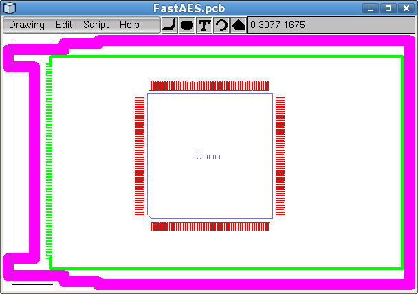 |
Figure 8G |
Viewed from layer 0, the footprint is now on the right layers, but the pins (1 to 208) still run counter-clockwise as if it were were mounted on the top side.
When you load a library object, you should be on the layer holding the objects you want to snap to grid. For schematic symbols and through-hole PCB footprints, this is layer 0. For surface-mount devices, this is layer 2. This assures these items will align themselves correctly with the drawing grid.
Mirroring Objects
To mirror an object, first select it, and then select Edit->Flip to mirror it around its vertical axis. There is no keyboard shortcut for this infrequent operation.
Congested layouts sometimes require extraordinary measures. Imagine this design requires some connections between the 208-pin component and the IO connector on the left. Assume only a smattering of these connections are to pins 1 to 52 along the component's bottom edge and that the majority of congestion results from connections to each of the next 52 pins, 52 to 104.
Consider that you can increase access to pins 1 to 52 without sacrificing much accessibility to pins 53 to 104 by rotating the footprint slightly:
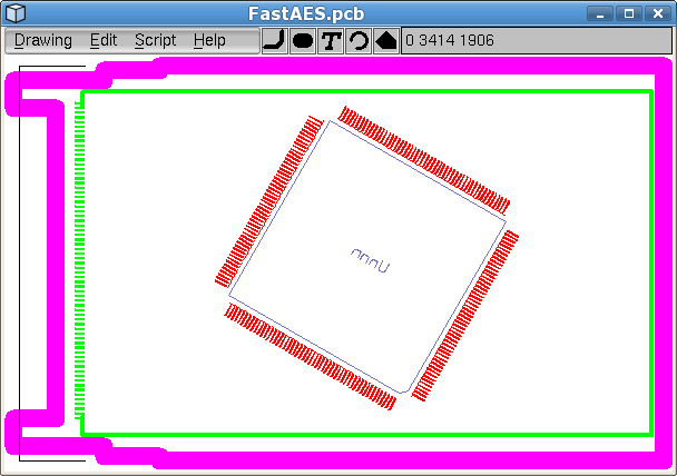 |
Figure 8H |
Rotating Objects
To rotate an object, first select it, and then select Edit->Spin to rotate counter-clockwise by the amount specified by in the Preferences dialog.
By default, the rotation in Spin Angle: is -90 degrees to accomodate the most common rotation, a quarter turn clockwise, but you can override this angle with any value from -180 to 180. The value you enter is rounded to the nearest 1/64th degree.
Observe the footprint has been mirrored and then rotated clockwise by 30 degrees to increase access to pins on the component's bottom edge.
To minimize accumulating roundoff errors when your design requires multiple crooked versions of a component, create each one with a single rotation from the original. E.g., to get 30- and 60-degree versions of a component, use separate 30- and 60-degree rotations instead of applying a second 30-degree rotation to the result of the first.
With simple, 90-degree rotations there is no roundoff.