Navigating Through Your Drawing
At its default resolution, 200 nanometers, HiWIRE® can accomodate drawing nearly a kilometer on a side. Viewing or modifying such huge drawings on your computer screen requires compromises ranging from:
Viewing the entire drawing at a scale where finer details become illegible.
Viewing a tiny portion of the drawing at the risk of loosing context for any changes you're making.
HiWIRE® allows you to pan and scroll a portion of your drawing through its viewport. If you tried any of the operations on the previous pages, you probably have discovered one or two ways to do this. Below, you'll find an exhaustive list.
Importantly, HiWIRE® eases the task of Zooming to allow you to step back from your work to gain context for a task and then return to a detailed view to finish it. In HiWIRE®, ZUI is always available. For example, you can use it in the midst of changing a line or positioning something you've just loaded from a library.
Panning and Scrolling
You can slide the drawing around in the viewport using the mouse. If the mouse is otherwise occupied, you can use the keyboard to move the viewport over the drawing to achieve the same goal.
Using the Mouse
Aim the cursor at the background, away from any specific item in your drawing, press the left mouse button, and drag the background around in the viewport with all its items attached.
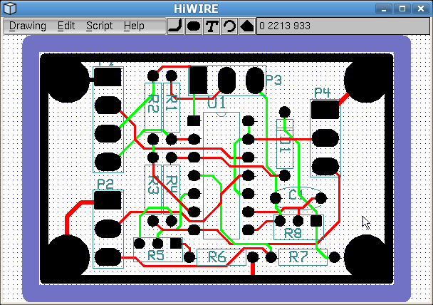 |
Figure 7A |
Above, the status line confirms nothing is picked. The left mouse button is pressed, and movement begins.
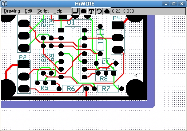 |
Figure 7B |
After dragging the background left and upward, the status line shows the cursor position has not changed with respect to the drawing.
Using the Keyboard
When you're using the mouse to copy, move, or change an item, you won't be able to use it to pan or scroll to another region of your drawing. Although you could stop what you're doing, move the drawing, and then resume where you left off, HiWIRE offers an alternative – you can jog the viewport with the cursor keys.
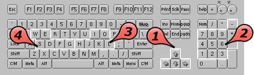 |
Figure 7C |
The cursor keys move the viewport in one of four directions.
The numeric keypad also supports diagonal moves using 1, 3, 7 and 9.
To good effect, a very popular editor uses the home keys, L, K and J along with their neighbor H to move right, up, down and left, respectively. HiWIRE offers these keys as a courtesy for touch typists.
For touch typists that mouse right-handed, G, D, F and S mirror this movement on the left-side home keys.
When you open an existing drawing, the viewport is positioned and zoomed to see the entire drawing.
When you start an new drawing, the viewport is positioned an the lower-left corner of the workspace, a virtual piece of paper about a kilometer on a side. If you try to move the viewport to see the edge of the paper, HiWIRE will resist your efforts and flash the screen in protest. If this is annoying, make sure you move the viewport well away from the edge before you begin to draw. One easy way to do this is to zoom out a few times, move the cursor to the center of the viewport and zoom back in. Zooming is described below.
Zooming In or Out
If your mouse sports a scroll wheel, you can use it to zoom in or out.
If not, you can do the same thing from the keyboard. Refer to Figure 7C:
To enlarge the drawing for more detail, use the plus key (+) next to the numeric keypad. To pull back for a wider view, use minus (–).
For some touch typists, I zooms In; O zooms Out.
For other touch typists, W takes a Wider view; E makes tiny things Easier to see.
Some operating systems promise to keep the active window (the one receiving mouse and keyboard input) atop all other windows. HiWIRE relies on this promise. It accelerates panning and scrolling by copying the portion of the viewport it drew earlier and fills in just a small extra sliver.
This works fine until the operating system reneges on its promise and plops a message box atop the HiWIRE viewport to tell you “You've got mail!” or “Your computer is at risk!” If HiWIRE scrolls before this message goes away, you'll get windows droppings in the viewport. Please understand this does not affect your drawing, only HiWIRE's rendering of it on your screen.
You can clean up the mess by zooming in and out or by pressing the 5 key on the numeric keypad to redraw the whole viewport. It is a price worth paying. A workaround would be to redraw the whole viewport for even a tiny move, but that soon becomes annoying.
More reliable operating systems with well thought out graphics support don't have this problem. Although they may bury HiWIRE's Viewport underneath multiple other windows, at least they are polite enough to tell HiWIRE about it.
Changing Working Layer
HiWIRE supports up to 256 layers, numbered 0, 1, …, 255. When nothing is picked the working layer is displayed in the status bar. We may also refer to the working layer as the current layer. When you add new objects to your drawing from the parts bin, they are placed in the working layer.
Suppose you somehow set the working layer to 2. We may say that you are working on layer 2, or we may even shorten it to say you are on layer 2.
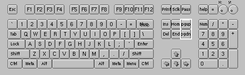 |
Figure 7D |
To increment the working layer, press Page Up on the six-key cluster.
To decrement the working layer, press Page Down.
HiWIRE layers are arranged in a modular sequence. That is, if you're working on layer 0, you can ascend 255 times to reach the last layer. If you then ascend one more time, you'll find yourself back on layer 0! Thus, to reach layer 255 from layer 0, it is easier to descend since a single keypress gets you there.
For reasons we'll describe below, most work centers around layer 0.
By convention in schematic drawings, component pins and their interconnections are drawn on layer 0. Ornamentation (stuff there mainly to make the components recognizable to a trained technician) is drawn on layer 255. Other layers can be used for a variety of purposes: Engineering notes, test procedures, testpoint voltages and waveforms, etc.
For circuit boards, signal layers are traditionally drawn on layers 0 and upward. Manufacturing and ancillary information: Silkscreens, solder masks, paste patterns, drill data, etc. are placed on layers 255 and down.
In circuit board drawings, there may not be a one-to-one correspondence between HiWIRE layers and physical board layers. Often, two or more HiWIRE layers are combined in unusual ways to generate a single piece of artwork used in fabrication.
This is only a preview. We'll revisit all this later.
Coloring Layers
In HiWIRE, coloring is mainly used to signify layer; objects on the same layer have the same color. Although HiWIRE uses a pretty reasonable color scheme, you can experiment with the colors assigned to each layer in the Preferences dialog.
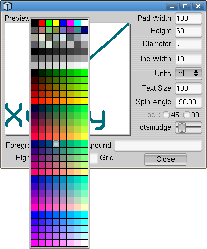 |
Figure 7E |
If you want to try a different background color, do that before fiddling with any of the layer colors:
Edit->Preferences… to display the dialog (if it's not already displayed).
Click the swatch left of Background to display a color sampler. Click one of the 255 other colors or type Esc to dismiss the sampler and retain the original color. Black or white are reasonable choices. Black may be better if you must deal with more than three or four layers at a time, but it is largely a matter of personal taste.
If you want a dot grid displayed, set the Grid to a contrasting color. You can make the grid invisible but retain its position snap effect by duplicating the background color.
After you've set the background, you can change the colors for each layer. Try to choose colors from the first rows in the sampler. There is a fairly complete palette, but contrast diminishes rapidly past the first few colors:
Move to the layer by pressing Page Up or Page Down with the cursor inside the main HiWIRE window.
Edit->Preferences… to display the dialog (if it's not still displayed).
Set the layer's Foreground color. Choose a pleasing distinct color because that's how objects on the layer will look to you most of the time. In the Preview pane, the line and text are rendered in the foreground color.
Similarly, select a Highlight color you can tolerate. The pad in the preview pane is rendered in the highlight color. The region where the pad and line overlap shows how an object will look when it is picked.
Color changes you make in the Preferences dialog are not permanent. The initial color scheme is controled by a Python module, Prefs.py. You can can edit the source code of this module to make permanent changes. More about that later.
Layer 0: the Unlayer
Usually, primitives on a specific layer can be manipulated (i.e., picked, lassoed, changed, moved, deleted, etc.) only when you're working on their layer.
Below, you'll learn how to designate a few other layers as a backdrop for the working layer, but you can look, but not touch, these backdrop objects. The backdrop is displayed only to give you context for tasks on the working layer.
Layer 0 is a notable exception. If you're working on layer 0, you can see and manipulate objects on any other layer. If you're working on another layer, you can see and manipulate objects on layer 0. Layer 0 is always visible; you can always manipulate objects there regardless of the working layer. To put it another way: Layer 0 is all layers, and all layers are layer 0.
Now, you may find this disturbingly reminiscent of the nihilist's “Nothing is everything, and everything is nothing”, but in HiWIRE this property of the unlayer can be put to good use.
For example, in multi-layer circuit boards, through-hole components can connect to any layer, and one way to handle this is to put their footprint pads on layer 0. The alternative is to tediously copy the pad from layer to layer to form a stack for each pad. Although this isn't that hard to do, a layer-0 pad is probably a better choice.
Multi-layer objects
While primitives exist only on a single layers, groups can contain primitives on multiple layers. Layering affects how you wrangle these objects in your drawing in sometimes surprising ways.
Lassoing
Lassoing is always layer selective. A lasso will only select objects that are solely on the working layer. The only way to lasso-select a multi-layer group is to do it on the unlayer.
Moving between layers
Moving between layers is no different than moving within a layer. Grasp the object (that is, pick it, press the left mouse button and drag it slightly to dislodge it from its current position), and press Page Up or Page Down while maintaining your grasp (keeping the mouse button pressed). When you've reached the destination layer, release the mouse button to deposit the object at its current location.
For example, HiWIRE's library only includes surface-mount footprints designed for component-side mounting. These footprints include layer-2 pads and layer-255 silkscreen decoration. High-density design often dictates components be installed on both sides of the board. A solder-side footprint requires pads on layer 1 and silkscreen on layer 254. To move the footprint to the opposite side of the board, grasp one of its pieces and press Page Down.
On which three layers could you be to start the task we just described? --answer--
After moving the footprint to the right layer, it needs to be “turned upside down”. How might you do this? --answer--
When moving an object between layers, it is best to start off on the object layer. You can always start off on layer 0, but don't be alarmed after you traverse the requisite number of layers and let go, the object disappears!
Moving objects display all their layers and maintain their position relative to the current layer. If you were on layer 0 when you began the example move and Page Down-ed yourself, the footprint would tag along with you to layers 1 and 254. But when you released the footprint it would seem to disappear because you'd be on layer 255 where neither layer 1 nor 254 are normally displayed.
Specifying Backdrop Layers
When laying out your drawing, it is often quite helpful to see layers other than the one you're working on. For example when connecting a sea of surface mount footprints using layer-2 lines it is nice to see the silkscreen annotation so you can distinguish U3 from U4 or U5. (We assume you use the prefix 'U’ for your circuit Units although you may actually prefer 'IC’ for your Integrated Circuits.)
On the Preferences dialog, you can enter a sequence of backdrop layers in the text box to the right of Background:. A comma-separated list is recommended although HiWIRE does its best to make sense of anything you enter.
To specify a specific layer, just enter the layer number.
To specify a layer relative to the current layer, prefix a + or –.
The unlayer is always displayed; you need not include 0 in your list.
For example, let's assume you're designing a 2-layer surface-mount board. When making connections on the bottom (solder side, layer 1), it's handy to see the layer-254 silkscreen of any components there. Likewise, when you move to the top (component side, layer 2), it helps to see the layer-255 silkscreen. Furthermore, to help place vias that interconnect the two layers, you may want to see the opposite layer.
To make this happen, enter 1, 2, +253 into Background: within the Preferences dialog. The first two entries assure that both conductor layers will always be displayed. The last entry assures that if the working layer is 1, layer 1+253 = 255 will be displayed; if you're working on 2, layer 2+253 = 255 will be visible.
In the backdrop list, earlier layers are given display priority over later ones. In our example, when working on layer 1, layer-2 objects will obscure ones on the silkscreen layer, 255. If you think silkscreen objects are paramount, use +253, 1, 2 instead. If the working layer appears in your list, don't worry, HiWIRE won't waste time drawing it twice.
In the wacky world of HiWIRE modular arithmetic, -3 and +253 are congruent, and 1, 2, +253 is exactly equivalent to 1, 2, -3. That is, to get from layer 2 to layer 255, you can ascend 253 times or descend thrice.